
News Single
Focus On Connecting And Cooling
Vapor Chamber Fin Heat Sink
Vapor Chamber Fin Heat Sink
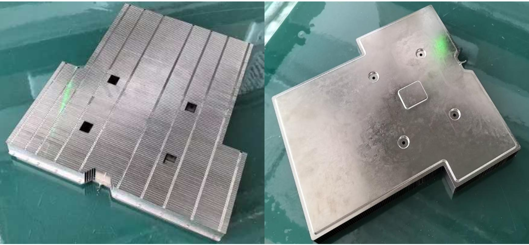
The VC fin heat-dissipation module consists of a vacuum-cavity VC vapor chamber and cooling fins, tightly joined by vacuum brazing. A VC is essentially a flattened, two-dimensional heat pipe, with a capillary structure and a phase-change working fluid housed in an internal vacuum environment. Once heat from the source reaches the VC evaporation surface, the working fluid vaporizes and rapidly spreads the hot-spot heat evenly across the entire plate; the heat is then transferred through the brazed interface to the outer fins and dissipated by forced convection.
We can deliver VC solutions paired with stacked aluminum fins, copper fins, or skived fins in a variety of combinations. These can be supplied as standalone modules or integrated with heat pipes to form a hybrid cooling system.
I. Core Performance Advantages
1. Two-dimensional planar temperature uniformity, greatly reducing spreading thermal resistance
Heat pipes provide one-dimensional heat conduction; a VC achieves omnidirectional heat transfer across a plane, keeping the plate-surface temperature difference within ≤2–3°C.
2. Ultra-high equivalent thermal conductivity
The equivalent thermal conductivity of VC phase-change heat transfer reaches 20,000–100,000 W/(m·K), far higher than pure copper at 395 W/(m·K), so heat spreads far faster than through solid-metal conduction.
3. Flat construction, suited to ultra-thin system designs
Ultra-thin VC base plates can go down to 2.0 mm, and the overall heat-sink height stays controllable — widely compatible with 1U/2U servers, portable industrial control equipment, and compact computing hardware.
4. Flexible and diverse combination options
The VC base plate can be paired with stacked aluminum fins, zipper fins, or copper fins, and can also be combined with skived heat sinks; weight, cost, and thermal performance can be flexibly balanced according to the power dissipation.
5. High interface reliability
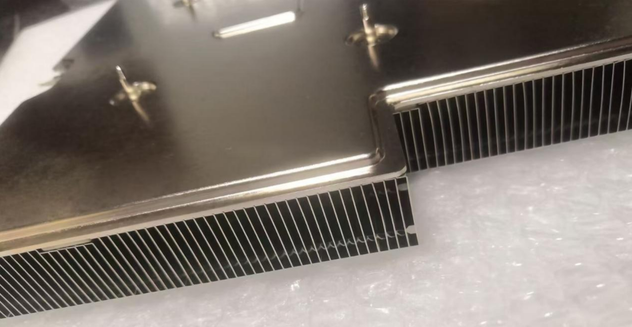
The VC and fins are joined by vacuum brazing with a high braze-coverage rate. The interface contains no thermal grease and no gaps, and withstands high- and low-temperature shock as well as mechanical vibration, meeting the needs of 24/7 continuous equipment operation.
6. Support for coordinated cooling of multiple heat sources
A large-area VC base plate can cover the main chip, memory, and power-supply circuitry at the same time, equalizing the temperatures of multiple heat sources and reducing temperature differences between points.
II. Complete Technical Specifications and Standard Parameters
1. Basic VC vapor chamber parameters
Base material: TU1 oxygen-free copper
Mainstream thickness specifications: 2.5 mm, 3.0 mm, 4.0 mm
Maximum formed size: 320 × 287 mm (CNC milling of custom contours available on request)
Internal structure: sintered copper powder / copper mesh wick
Operating temperature range: 0°C to 120°C
2. Fin pairing options
1) Stacked aluminum fins
Fin thickness 0.2–0.3 mm, fin pitch 1.5–2.1 mm; lightweight and highly cost-effective.
2) Zipper fins
High structural rigidity and moderate air resistance; suitable for standardized server heat sinks.
3) Copper fins / skived fins
Selected for ultra-high-power models to further increase heat-exchange capability.
3. Machining accuracy standards
VC base-plate flatness ≤0.04 mm/100 mm, ensuring full contact with the heat source;
Fin braze position tolerance ±0.08 mm;
Overall dimensional tolerance ±0.1 mm;
100% air-tightness leak testing on finished VCs, eliminating any leakage of the internal working fluid.
III. Raw Material Selection: Material Types
1. VC base plate: TU1 oxygen-free copper
Its low oxygen content gives excellent weld sealing and good sintering stability of the capillary structure. It is not prone to generating non-condensable gases, which avoids performance decay over long-term use. Ordinary T2 copper is used only for simple, low-requirement solutions.
2. Fin base materials
6063 aluminum fins: lightweight with a clear cost advantage; the first choice for the vast majority of air-cooled modules;
C1100 copper fins: selected for extreme cooling requirements and high-power equipment, at the expense of increased weight and cost.
IV. Full Production Process
CFD → DFM → VC vapor chamber forming → fin stamping → precision cleaning of components → fixture positioning of VC and fins → vacuum braze bonding → CNC finish machining → deburring → surface treatment → sample performance testing → final inspection and packaging
1. CFD simulation: models the heat-source distribution and airflow field to optimize fin density and layout;
2. Vacuum brazing: welding in an oxygen-free environment prevents oxidation of the copper and ensures a tight interface between the VC and the fins;
3. 100% air-tightness inspection: prevents VC leakage — once fluid leaks out, the phase-change cycle fails and heat-sink performance drops sharply.
Surface treatment:
1. VC base-plate area: electroless nickel plating
Seals the surface from air to prevent copper oxidation and improves braze wettability; also prevents copper-oxide powder generated during long-term operation from contaminating the system.
2. Aluminum fins: black anodizing, 12–18 μm
Increases the thermal emissivity, provides rust and corrosion protection, and looks good; salt spray ≥168 h.
3. Copper fins: nickel plating
Prevents copper from oxidizing and darkening, extending service life.
V. Applicable Industries and End-Use Applications
1. Computing server sector
1U/2U rack servers, AI edge computing cards, GPU accelerator cards, industrial server CPU heat sinks;
2. Industrial automation electronics
High-power industrial control motherboards, inverter main-control modules, laser driver power supplies;
3. Automotive electronics
In-vehicle computing platforms, autonomous-driving domain controllers;
4. High-end communications equipment
High-power 5G base station units, high-density communications power modules.
VI. Product Compliance Certifications
1. Management system certifications
1) ISO 9001:2015 quality management system certification;
2) ISO 14001 environmental management system.
2. Environmental material certifications
1) RoHS 2.0 hazardous substance testing ;
2) Material certificates and SGS test reports provided for the aluminum raw material.
3. Third-party performance testing
1) Salt-spray corrosion resistance test;
2) Air-tightness leak testing.
VII. Prototyping & Mass-Production Delivery Notes
1. Custom irregular VC contours and non-standard fin layouts are supported;
2. Fin height and fin density can be matched to the customer’s system height, airflow, and power dissipation;
3. Both sample trial production and volume manufacturing are supported; complete modules can be delivered together with spring screws and thermal pads;
4. Extended options: the VC fin module can be further combined with heat pipes or a compact water-cooling block to create a hybrid cooling solution.
Q1: What is the core difference between a VC heat sink and a heat-pipe heat sink?
A: A heat pipe conducts heat one-dimensionally and linearly — heat can only travel along the pipe, so temperature blind spots easily appear on the base plate. A VC vapor chamber conducts heat two-dimensionally across a plane, so heat can spread in any direction within that plane, giving much stronger temperature uniformity and significantly reducing the hot-spot temperature difference at the chip. High heat-flux density, multiple heat sources, and compact equipment should give priority to a VC solution.
Q2: How do I choose between a VC heat sink and a skived heat sink?
A: The advantage of skived fins is one-piece forming with zero interface thermal resistance, which suits purely air-cooled, high-power equipment. The strength of a VC module is flattening out locally concentrated hot spots, which suits scenarios where the chip heat source is very small and the heat is highly concentrated. The two can also be used together: a VC base plate paired with skived fins delivers maximum cooling performance.
Q3: What medium is inside the VC? Does the working principle degrade over time?
A: The interior is filled with pure water as the phase-change working fluid, which undergoes an evaporation–condensation cycle under vacuum. As long as the cavity does not leak and no non-condensable gases are generated, it will in theory operate stably over the long term; strict leak testing before shipment safeguards service life.
Q4: What is the minimum thickness a VC can be made to?
A: The standard thickness in volume production is 2.0 mm; ultra-thin custom versions can reach 1.5 mm. Ultra-thin VCs place extremely high demands on machining and welding processes, so costs rise.
Q5: How are the VC and the fins joined — riveting or welding?
A: The standard solution uses vacuum brazing, which gives a tight overall interface and stable thermal resistance. Riveting alone is not recommended, as riveted joints contain gaps and their thermal resistance keeps rising under long-term operating conditions.
Q6: Can a VC be made in an irregular, non-standard shape?
A: Yes. After the VC base plate has been welded, custom contours can be CNC milled to avoid interference with capacitors, connectors, and other components inside the chassis.
Q7: Are there any mounting-orientation restrictions for VC heat sinks?
A: A VC with a sintered capillary structure has good anti-gravity capability and works stably in all conventional mounting orientations; extreme inverted operating conditions require confirmation through thermal design evaluation beforehand.
Q8: What happens if a VC leaks?
A: Once the vacuum environment is compromised, the phase-change cycle fails and the VC becomes equivalent to an ordinary copper plate, so cooling capability drops sharply. All of our products undergo 100% leak testing, and leakage very rarely occurs in normal use.
Q9: What is the maximum long-term operating temperature limit?
A: Continuous long-term operation at ≤110°C is recommended; short-term peak temperatures should not exceed 125°C. Excessive temperatures readily accelerate the internal generation of non-condensable gases and shorten service life.
Q10: Why does the VC base plate need nickel plating?
A: The VC base material is copper, which oxidizes and darkens easily when exposed to air. Nickel plating prevents corrosion while also improving braze wettability with the fins, safeguarding welding yield.
Q11: How do I choose between aluminum and copper fins?
A: Choose aluminum fins to minimize weight and control cost; choose copper fins where equipment power dissipation is extremely high, temperature-rise targets are stringent, and the budget allows.
Q12: How long is the prototyping lead time for a VC heat sink?
A: After the drawings are confirmed, the complete set of processes — VC machining, fin brazing, and finish machining — gives a sample lead time of 18–28 days; entirely new custom-shaped structures extend this somewhat.


 Send Email
LiveChatclose